
PH 55–550 S
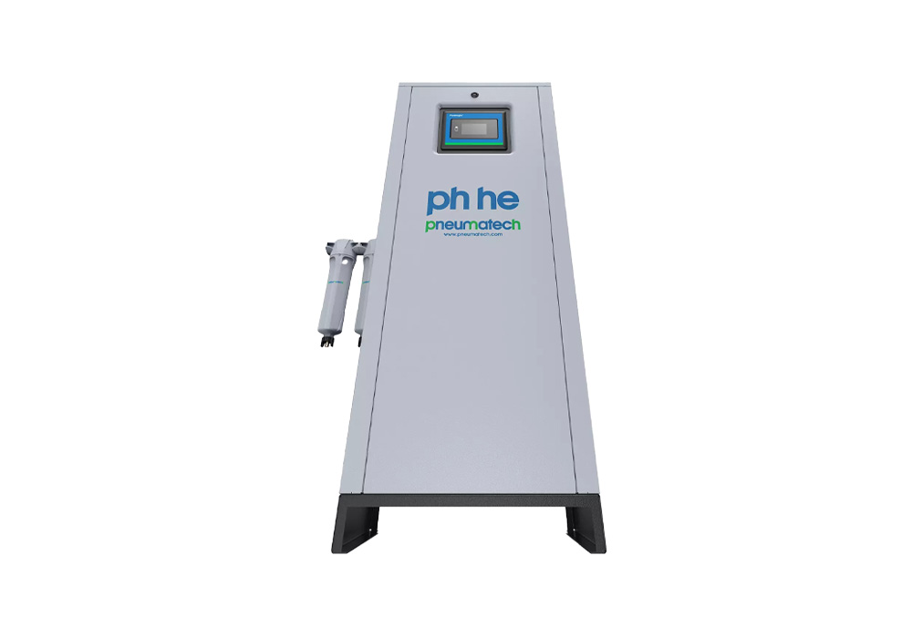
Introduction
Key Benefits
Flexible Installation
Two Dew-Point Options
Counter-Current Regeneration
Standard Filtration
Wide Capacity Range
Reliable Valve Design
Why Choose pH 55–550 S Adsorption Dryers?
Moisture in compressed air can cause corrosion, freezing, pneumatic equipment problems and process-quality issues. Heatless adsorption dryers remove moisture by passing compressed air through a desiccant that captures water vapour.
The PH 55–550 S regenerates the saturated desiccant using a portion of dried and expanded purge air. This cyclic process enables continuous compressed-air drying while maintaining pressure dew points of -20°C or -40°C, depending on the selected configuration.
Technical Specifications
Model |
Version PDP -40°C |
|---|---|
Nominal volume flow at dryer inlet (m3/h) |
|
PH 55 S |
90 |
PH 75 S |
126 |
PH 95 S |
162 |
PH 120 S |
198 |
PH 140 S |
234 |
PH 190 S |
324 |
PH 230 S |
396 |
PH 275 S |
468 |
PH 350 S |
594 |
PH 420 S |
702 |
PH 550 S |
936 |
How Does the PH 55–550 S Work?
The PH 55–550 S uses a two-vessel heatless adsorption process to continuously remove moisture from compressed air.
Step 1 – Moist Compressed Air Entry
Moist compressed air enters the active adsorption vessel.
Step 2 – Filtration
Pre-filtration helps protect the desiccant from contaminants entering with the compressed air.
Step 3 – Adsorption
The compressed air passes through the desiccant, which captures water vapour.
Step 4 – Dry Air Delivery
The dried compressed air exits the active vessel and enters the plant air network.
Step 5 – Desiccant Saturation
The desiccant gradually accumulates moisture during the adsorption cycle.
Step 6 – Counter-Current Regeneration
A portion of dried compressed air is expanded and directed through the saturated vessel in the opposite direction to the drying airflow.
Step 7 – Vessel Switching
The valves switch the functions of the two vessels so that the regenerated vessel begins drying while the other enters regeneration.
Step 8 – Continuous Drying
The alternating cycle provides continuous production of dry compressed air.
Why Choose PH 55–550 S?
-20°C and -40°C Dew-Point Options
The PH 55–550 S is available in two pressure-dew-point configurations, allowing customers to select the appropriate drying level for their application.
Advanced Energy Management
Compressor synchronization and purge-nozzle optimization help reduce unnecessary energy and purge-air consumption during dryer operation.
Optimized Purge Nozzles
Two purge nozzles are incorporated to optimize purge-air expansion during regeneration, helping improve overall operating efficiency.
Reliable Valve Switching
The unique manifold uses pilot-air-controlled 3/2-way valves designed for fast and reliable switching between drying and regeneration cycles.
Spring-Loaded Desiccant
The desiccant is spring-loaded to minimize movement and reduce the risk of crushing during operation, supporting reliable long-term performance.
Counter-Current Regeneration
Regenerating against the drying airflow direction supports efficient moisture removal and helps maintain consistent dry-air performance.
Easy Desiccant Servicing
Desiccant bags can be accessed from the top, simplifying routine servicing and replacement.
Real-Time Monitoring
The advanced controller provides visibility into machine status, pressure, valve operation and maintenance requirements.
Standard Pre- and After-Filters
Pre- and after-filters are supplied as standard, helping protect the dryer and maintain suitable compressed-air quality
Features & Configuration Options
Drying Technology
- Heatless adsorption
- Two-vessel operation
- -20°C pressure dew point
- -40°C pressure dew point
- Counter-current regeneration
- High-quality desiccant
Energy Management
- Compressor synchronization
- Two optimized purge nozzles
- Optional PDP control
- Efficient purge-air management
Mechanical Construction
- Extruded aluminium profile
- Spring-loaded desiccant
- Robust valve manifold
- Pilot-air-controlled 3/2-way valves
- Designed for transportability and mounting
Filtration
- Standard pre-filter
- Standard after-filter
Control & Monitoring
- Advanced controller
- Machine-status monitoring
- Pressure monitoring
- Valve-status indication
- Maintenance indication
- Optional PDP monitoring
- Remote alarms/warnings through available voltage-free contacts
Installation Options
- Standard industrial installation
- Optional wall-mounting kit for PH 55–140 S
- Compact extruded-profile construction
The current product information lists wall mounting and PDP control as the principal options.
Industrial Applications

Automotive Manufacturing

Machine Tools

Pharmaceutical Manufacturing

Textile Manufacturing

Food & Beverage
Frequently Asked Questions
What is the PH 55–550 S?
What pressure dew points are available?
What is the flow range?
What is the difference between PH 55–550 S and PH 55–420 HE?
How should the right PH 55–550 S model be selected?
Can Atcorp help select and supply the PH 55–550 S?
Related products
Oil-Injected, Rotary Screw Compressor
CPC Series 40-60 HP
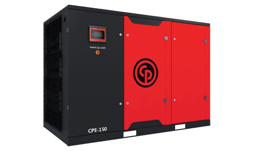
Oil-Injected, Rotary Screw Compressor
CPE Series 150 HP
Oil-Injected, Rotary Screw Compressor
CPF Series 180-220 HP
Oil-Injected, Rotary Screw Compressor
CPF Series 270-340 HP
Oil-Injected, Rotary Screw Compressor