
Evaporative Cooling Towers
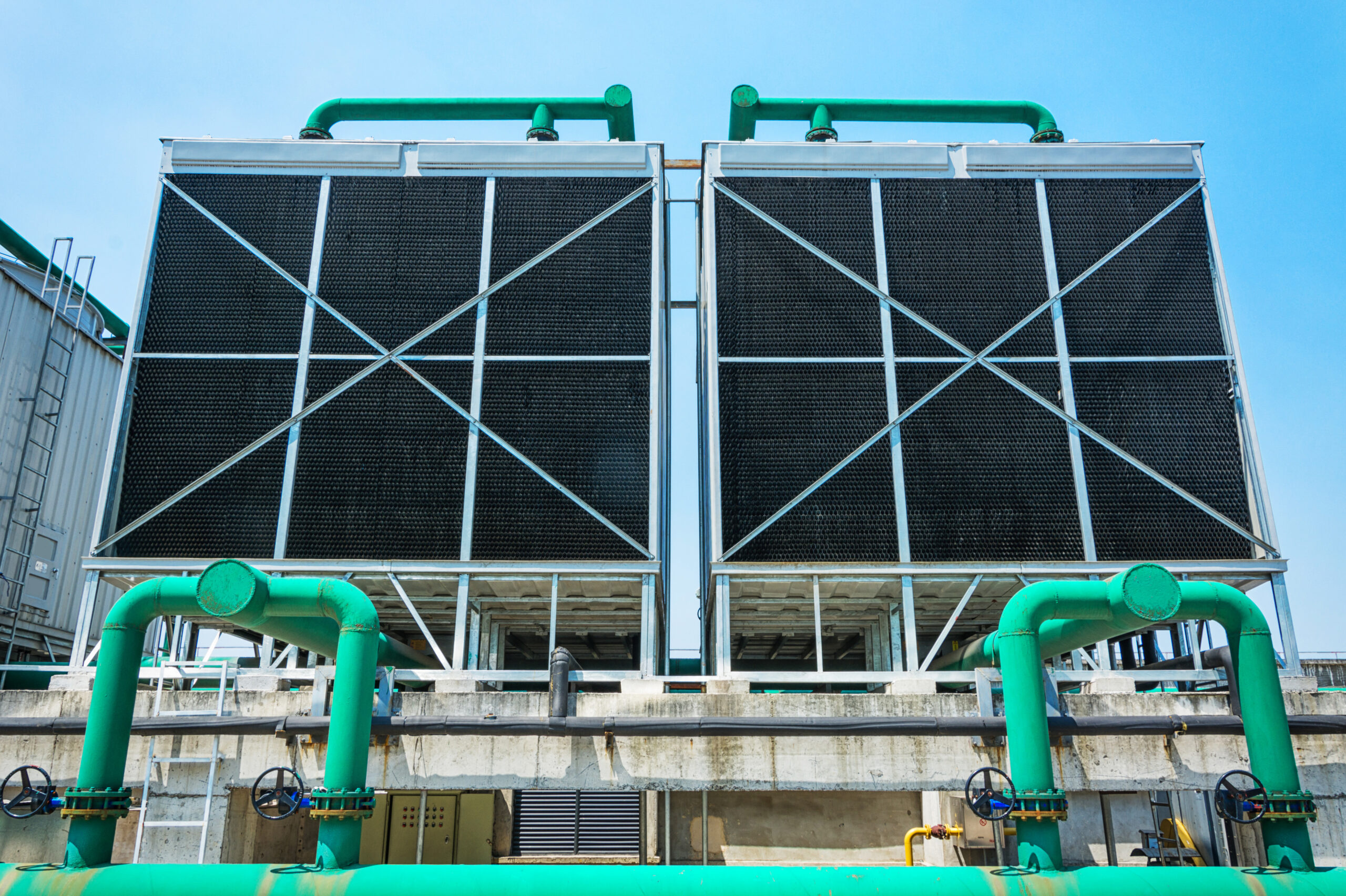
Introduction
Key Benefits
Closed-Circuit Cooling
Corrosion-Resistant Construction
Low Operating Noise
Efficient Heat Transfer
Lightweight Casing
Energy-Efficient Fans
Why Choose Evaporative Cooling Towers?
Technical Specifications
| Specification | Details |
| Tower Type | Closed-Circuit Cooler |
| Cooling Principle | Evaporative Heat Rejection |
| Airflow Design | Induced Draft |
| Airflow Direction | Counterflow |
| Process Fluid Circuit | Closed Coil Circuit |
| Tower Casing | FRP |
| Supporting Structure | Hot-Dip Galvanized Steel |
| Fill Material | Rigid PVC |
| Fill Design | Honeycomb |
| Fill Flute Height | 6 / 12 / 19 mm |
| Fill Sheet Thickness | 1.0 / 1.2 mm |
| Fan Type | Induced-Draft Axial |
| Fan Pitch | Adjustable |
| Fan Materials | Plastic / FRP / Aluminium Alloy |
| Fan Motor | Totally Enclosed Weatherproof |
| Motor Mounting | Adjustable Base Inside Fan Stack |
| Inspection Access | Inspection Doors |
| Process Cooling | Indirect / Closed Circuit |
| Water Distribution | Sprinkler / Nozzle System |
| Drift Control | Drift Eliminator |
| Maintenance Access | Lift-Out Strainer & Sump Access |
How Does an Evaporative Coil Cooling Tower Work?
An evaporative coil cooling tower removes heat from the process fluid through an indirect evaporative cooling cycle.
Step 1 – Process Fluid Circulation
The hot process fluid enters the closed cooling coil inside the tower.
Step 2 – Water Distribution
Cooling water is distributed over the outside surface of the coil.
Step 3 – Airflow Generation
The induced-draft axial fan draws atmospheric air upward through the tower.
Step 4 – Heat Transfer
Heat moves from the process fluid through the coil wall into the cascading cooling water.
Step 5 – Evaporation
A small portion of the cooling water evaporates, carrying heat away with the moist air.
Step 6 – Atmospheric Heat Rejection
Warm, moisture-laden air is discharged from the top of the tower.
Step 7 – Process Fluid Cooling
The cooled process fluid exits the coil and returns to the connected industrial process.
Step 8 – Continuous Operation
The cycle repeats continuously to maintain the required process-fluid temperature.
Why Choose Evaporative Coil Cooling Towers?
Closed-Circuit Process Cooling
The process fluid remains inside the coil, reducing direct exposure to atmospheric contaminants and evaporative water.
Efficient Evaporative Heat Transfer
The combination of water cascading over the coil and upward airflow provides effective heat rejection through evaporation.
Induced-Draft Counterflow Design
Air moves upward while water moves downward, creating an efficient counterflow heat-transfer arrangement.
FRP Corrosion-Resistant Casing
The fiberglass-reinforced polyester casing is lightweight, corrosion-resistant and does not require painting.
Robust Structural Frame
Hot-dip galvanized steel supporting structures help minimize rust and corrosion while providing long-term structural strength.
Energy-Efficient Airflow
Induced-draft axial fans with adjustable pitch are designed for efficient airflow with low operating noise.
High-Surface-Area Fill
Honeycomb PVC fill divides the air and water streams into multiple paths, increasing contact time and supporting heat transfer.
Easy Maintenance Access
Inspection doors provide access for internal inspection, float-valve adjustment, strainer cleaning and sump flushing
Construction & Component Features
Structure
- Hot-dip galvanized steel supporting frame
- Corrosion-resistant construction
- Designed for long-term industrial service
Casing
- Fiberglass Reinforced Polyester (FRP)
- Lightweight construction
- Corrosion resistant
- No painting required
- Easy assembly
Air Distribution
- Induced-draft axial fan
- Adjustable-pitch fan blades
- Dynamically balanced fan
- Low-noise operation
- Corrosion-resistant fan material options
- Totally enclosed weatherproof motor
- Adjustable motor base
Water Distribution
- Sprinkler distribution system
- SCSP nozzles
- PVC honeycomb fill
- Drift eliminator
- Lift-out strainer
- Accessible sump
Fill Options
- 6 mm flute height
- 12 mm flute height
- 19 mm flute height
- 1.0 mm sheet thickness
- 1.2 mm sheet thickness
Industrial Applications

Process Cooling

Chemical Processing

Pharmaceutical Manufacturing

Food Processing

Industrial Heat Exchangers
Frequently Asked Questions
What is an evaporative coil cooling tower?
How is an evaporative coil cooling tower different from an open cooling tower?
How does the cooling process work?
What type of airflow does the tower use?
How is an evaporative coil cooling tower selected?
Can Atcorp supply evaporative coil cooling towers in India?
Related products
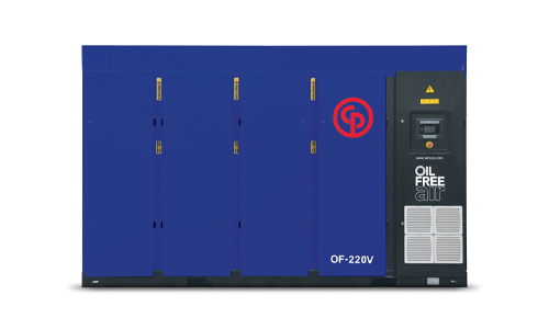
Oil-Injected, Rotary Screw Compressor
CPC Series 40-60 HP
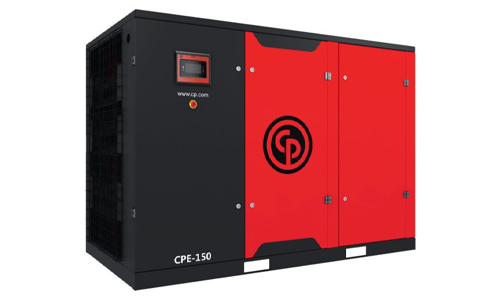
Oil-Injected, Rotary Screw Compressor
CPE Series 150 HP
Oil-Injected, Rotary Screw Compressor
CPF Series 180-220 HP
Oil-Injected, Rotary Screw Compressor
CPF Series 270-340 HP
Oil-Injected, Rotary Screw Compressor